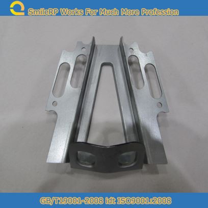
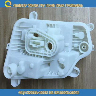
Our Company is one of the best factories of Car Parts CNC Prototype Model Machining in Shenzhen,China.
|
Brand |
SMILE RP |
|
Prototype Name |
Aluminum Prototypes |
|
Process Method |
CNC Machining,CNC Milling,CNC Turning |
|
Drawing File |
Dwg,pdf,step,stp,igs,x-t, stl |
|
Tolerance |
+/-0.01mm |
|
Surface Finish |
Sandblast,Anodized,Polish |
|
Package |
Pearl Wool,Hardcarton,Wooden Case |
|
Place Of Origin |
China(Mainland) |
|
Other Process Methods |
CNC Plastic Rapid Prototype ,Vacuum Casting,SLA SLS 3D Printing,Sheet Metal Parts Process |
|
Plastic Process Material |
abs,pc,nylon(PA),acrylic(PMMA),pp,pom,Teflon,PA+GF30, Fire-proofabs ul94-v0,abs+pc,pc+gf30,pvc,silicone rubber |
|
Metal Process Material |
aluminum6061T6,Ly12,7075,6082,stainless steel,carbon steel, ,brass,copper,iron,sheet metal, |
|
Delievery Time |
3-7 work days (Prototypes) |
|
Payment Terms |
TT,Paypal,Western Union (40% deposite,60% before ship) |
|
Transport |
DHL,UPS,TNT,FEDEX,EMS For Choice |
|
Main Exporting Country |
America,Canada,Germany,Australiq,Japan,Israel,Franch, Brazil,Switzerland,Italy |
The follow picture shows some cnc aluminum parts that we made before.



If you want to Kown more about CNC Machining Parts and cost.
please contact us
Steven Song(The Sales Manager)
Email: steven@smilecnc-china.com
You will get a quotation within 2-3 hours after we receive your inquiry at work days.
Look forward to your Join.
Knowledge:As for Car Parts CNC Prototype Model Machining,what should we pay attention to in the Processing
(1) Check whether the lubricating oil in the lubricating oil pump behind the milling machine is sufficient, whether the air compressor is turned on, and whether the mechanical oil used for cutting fluid is sufficient before each boot.
(2) When turning on the main power supply, first turn on the total power supply, then press the opening button in the CNC power supply, rotate the emergency stop button clockwise, and wait for the milling machine to test all functions(a row of red lights on the lower operating panel is turned off). Press the machine button to reset the milling machine and put it on standby.
(3) When operating manually, attention must be paid at all times. Before moving in the X and Y directions, the Z axis must be placed in the lifting position. During the movement process, you can not only see the changes in the coordinates of the CRT screen, but you must observe the movement of the tool. When the tool moves in place, you can watch the CRT screen for fine-tuning.
(4) In the programming process, for beginners, use G00 instructions as little as possible, especially in the three-axis linkage of X, Y, and Z. When walking an empty knife, the movement of the Z axis should be carried out separately from the movement of the X and Y axes, that is, more knives and less oblique insertions. Sometimes the tool will touch the workpiece and the tool will break due to oblique insertion.
(5) When using a computer for serial communication, it must be done: open the milling machine first, and then open the computer; Turn off the computer first, turn off the milling machine later. Avoid milling machine in the process of switching, due to the instantaneous change of current and impact the computer.
(6) When using the DNC(transfer of programs between the computer and the milling machine) function, pay attention to the memory capacity of the milling machine. In general, the total number of bytes of the program transmitted from the computer to the milling machine should be less than 23 kB. If the program is relatively long, it must be processed by the computer while transmitting, but the program segment number must not exceed N9999. If there are more than 10,000 program segments, you can cancel the program segment number with the program editing function in MASTERCAM.
(7) When there is an alarm on the milling machine, it is necessary to find out the reason according to the alarm number and remove the alarm in a timely manner. It can not be turned off, otherwise it is still in the state of alarm after the boot. Using the edge finder pair knife, the detailed steps are as follows:
(1) X, Y pair knife
(1) The workpiece is mounted on the machine tool platform through a fixture. When the precision part is clamped, the measurement position of the edge finder should be left on all four sides of the precision part.
2 Move the worktable and the spindle quickly so that the edge finder head is close to the left side of the workpiece;
3 Instead of fine-tuning the operation, let the tester slowly contact the left side of the workpiece until the edge finder lights up. Note the X coordinate value in the machine's coordinate system at this time, such as -310.300;
4 Lift the edge finder to the upper surface of the workpiece, quickly move the worktable and the spindle, so that the probe is close to the right side of the workpiece;
5 Instead of fine-tuning the operation, let the tester slowly contact the left side of the workpiece until the edge finder lights up. Note the X coordinate value in the mechanical coordinate system at this time, such as -200 .300;
6 If the head diameter is 10mm, the workpiece length is -200.300-(-310.300) -10 = 100, According to this, the X coordinate value of the origin W of the workpiece coordinate system in the machine tool coordinate system is -310.300 +100 / 2 +5 = -255.300;
7 Similarly, the Y coordinate value of the origin W of the workpiece coordinate system in the mechanical coordinate system can be measured.
(2) Z pair knife
(1) Remove the edge finder and install the tool used for processing on the main axis;
2 The Z axis setter(or the fixed height of the knife block, the same below) is placed on the plane on the workpiece;
3 Move the spindle quickly, let the tool end face close to the top surface of the Z axis setter;
4 Instead of fine-tuning the operation, let the tool end surface slowly contact the surface of the Z axis setter until its pointer indicates zero position;
5 Note the Z value in the machine tool coordinate system at this time, such as -250.800;
If the height of the Z axis setter is 50mm, the Z coordinate value of the origin W of the workpiece coordinate system in the mechanical coordinate system is -250.800-50-(30-20) = -310.800.
(3) Enter the measured X, Y, and Z values into the machine tool workpiece coordinate system storage address(usually using the G54-G59 code to store knife parameters).
3, pay attention to the following issues in the operation of the knife:
(1) adopt the correct tool for the knife according to the processing requirements and control the error of the knife;
(2) In the process of the knife, the accuracy of the knife can be improved by changing the fine-tuning feed;
(3) Care must be taken when handling knives, especially to pay attention to the direction of movement and avoid collision hazards;
(4) The knife data must be stored in the storage address corresponding to the program to prevent serious consequences from calling errors.
Second, according to the actual size and position of the tool, the tool radius compensation value and tool length compensation value are entered into the storage location corresponding to the program. It should be noted that the correctness of the compensation data, the correctness of the symbol, and the correctness of the location of the data will threaten the processing, resulting in the risk of collision or scrap of the processing.
Hot Tags: car parts cnc prototype model machining, China car parts cnc prototype model machining suppliers, manufacturers, factory, Machinery Aluminum Parts CNC Machining CNC Milling, Cnc rounter service, Precision Aluminum Parts CNC Machining, Auto Parts 5 Axis CNC Milling, Precision Aluminum Parts CNC Milling, Aluminum prototype cnc machining with high accuracy