


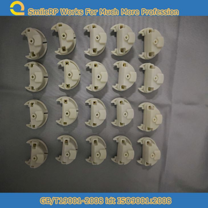
CNC conversion can be divided into manual conversion and automatic conversion. Manual programming is the process of manually calculating tool paths and programming machining programs. Automatic transformation is the use of computers to calculate the trajectory of tool movement through automatic transformation software. The advantages of these two programming methods are that manual programming is convenient and economical, while automatic programming has higher accuracy.
For some complex parts, due to their complex processing technology and the need for more programs, manual and automatic programming can be chosen.
1, Specific programming methods
(1) Manual programming
Manual programming refers to the manual completion of all tasks related to CNC programming. For workpieces with relatively simple processing shapes, the computational complexity is small, the program is short, and manual programming is fast and simple. Manual programming for complex shaped workpieces can be challenging and sometimes even impossible to achieve. Generally speaking, the contour of a workpiece composed of straight lines and arcs is manually programmed, while the contour composed of non circular curves and tabular curves is automatically programmed.
(2) Automatic programming
Automatic programming uses a computer for CNC machine tool programming, which automatically performs numerical calculations, writes part machining program sheets, automatically prints out machining program sheets, and records the programs on perforated paper tapes or other CNC media.
2, Automatic programming of complex parts
(1) Start NX6.0. Double click on the icon of UGNX6.0 to enter the UGNX6.0 interface.
(2) Open the model file. Select the [File] - [Open] command from the main menu, select the correct path and file name in the automatically popped up "Open" dialog box, click the "OK" button, and open the part model.
(3) Enter the processing module. Click on the [Start] - [Processing] command, then select "mill-Contour" in the "CAM Settings to be Created" section of the [Processing Environment], click "OK" to enter the processing module.
(4) Setting of the workpiece origin coordinate system
Click on the geometric view in the bottom right corner of the screen, and a dialog box for "Operation Navigator Geometry" will pop up. Double click on the "MCS-MILL" button and select "Auto Judging" from the drop-down menu in the "Machine Coordinate System". Click on the surface of the workpiece boss with the mouse. Select "Plane" from the "Safety Setting Options" drop-down menu in the "Gap" dialog box, click on the "Specify Plane" icon, click on the surface of the workpiece protrusion with the mouse, enter 10 in "Bias", and click "OK".


